The 10G OTN Digital Wrapper IP Core offers 10G/s client transport rate over Optical Transport Network (OTN), specified by ITU-T G.709 recommendation.
Description
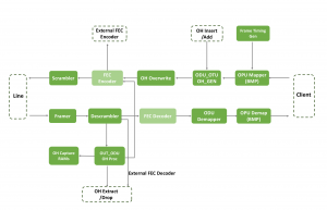
In the source direction data is transferred from the client clock to the line clock for ODU/OTU frame generation through an asynchronous fifo. The frame timing generator block generates row and column counts and alignment pulses to synchronize payload mapping, overhead insertion, FEC encoding and scrambling. The OPU Mapper block maps the input data into the OPU payload and calculates the overhead bytes and maps them into the overhead region with BMP or AMP. The ODU_OTU Overhead Generator (ODU_OTU OH Gen) block generates all overhead fields. OH bytes are received over an external OH insert interface bus. Maintenance signals are generated as consequent actions from defects detected by the sink direction and are inserted by the OH overwrite block. The OH overwrite block can overwrite any OTU/ODU/OPU overhead byte with software configured values. FEC insertion is optionally inserted from an external FEC encoding interface. The OTUk frame is then scrambled before sending to the line interface.
In the sink direction, line data is aligned by the Framer based on a programmable FAS. The framer generates row and column counts and alignment pulses to synchronize subsequent modules for performing descrambling, FEC decoding and extraction of overhead and payload data. The OTUk frame is then de-scrambled and passed to an optional FEC module which interfaces to an external FEC processor. The OTU_ODU overhead processor (OTU_ODU OH Processor) block extracts overhead bytes for processing by software. Overhead bytes are stored in the OH capture RAM for access by software. Alarms are processed. The OPU demapper block extracts payload data and OPUk overhead information if AMP mapped. The OPU overhead bytes are stored in the OH capture RAM and are optionally sent to an OH extract interface for external processing. Data is passed through an asynchronous fifo for transfer to the client on a client clock.
Block Diagram
For all Precise-ITC OTN digital wrappers, they support the following features and processing functions.
- Compliant with G. 709 (2012) and G.798
- Small footprint suitable for ASIC or FPGA realization
- Supported bus width options: 10G – 4 or 8 bytes, 40G – 16 or 32 bytes, 100G – 40 or 64 bytes
- OTU/ODU/OPU OH processing and insertion
- Optional processor interface with 32-bit registers
- Transmitter maps either arbitrary payload (OPUk payload area) or OPUk (with OH)
- Optional 32-byte OPUk fixed stuff mapping
- OPU payload mapping with BMP or AMP Mapping of ODTUG (PT=21) support requires external ODTUk.ts module to provide OPU OH and GMP mapping of payload. *AMP is not applicable to OPU4
- Transmitter maps either arbitrary payload (OPUk payload area) or OPUk (PSI bytes are configurable through software registers
- ODU and OTU OH generation including alarms
- OTU OH fields are configurable through software registers. Fields include FAS, SM, GCC0 and reserved bytes
- ODU OH fields are configurable through software registers. Fields include TCM1-6, FTFL, PM, EXP, GCC1-2, APS/PCC, and reserved area
- In OPUk mode, OPUk overhead is input on a dedicated bus.
- Supports G.709 round-trip-delay measurement using PM and TCM overhead as source or loopback node
- Optional FEC generation (with external processor). If disabled, FEC field is filled with zeroes
- OH insertion channel with byte mask to allow external module to generate any OTU/ODU/OPU overhead bytes. Column, row, and MFAS counts are provided as ports to an external module
- All OTU/ODU/OPU OH fields can be overwritten via software byte map. Each field includes byte mask to enable/disable overwrite
- Optional scrambling of OTU using frame synchronous scrambler. Generating polynomial is 1 + x + x3 + x12 + x16
- ODUk/OTUk frame alignment with programmable FAS field.
- Optional fixed stuff removal
- Programmable threshold count values for detection of OOF, LOF, OOM, LOM
- OTU and ODU OH processing, including detection of faults and errors
- g. OTUk-AIS, ODUk-AIS/OCI/LCK, OPUk-AIS detection and processing
- Optional descrambling of OTU using frame synchronous scrambler. Generating polynomial is 1 + x + x3 + x12 + x16
- Optional FEC processing (with external processor)
- Receiver de-maps either arbitrary payload (OPUk payload area) or OPUk (with OH). In OPUk mode, OPUk overhead is output on dedicated bus
- OPU payload de-mapping* with BMP or AMP. De-mapping of ODTUG (PT=21) support requires external ODTUk.ts module to process OPU OH. *AMP not applicable to OPU4
- Capture of TCMi, PM, GCC, APS/PCC bytes to register-mapped memory for software processing. Entire TTI signal is captured for SM, PM, and each TCMi
- Capture of all OTU/ODU/OPU OH fields to register-mapped memory block for software processing of static and slow-changing fields
- Supports G.709 round-trip-delay measurement using PM and TCM overhead as source or loopback node
- OH extract interface to allow external module to read all OTU/ODU/OPU overhead bytes. Output column, row, and MFAS counts are provided for alignment
- 32-bit counters for stats and error collection
The following OTU layer alarms and errors are detected :
- OOF/LOF/OOM/LOM
- AIS – Alarm Indication Signal
- IAE – Incoming Alignment Error
- BDI – Backward Defect Indication
- TIM – Trace Identifier Mismatch
- BEI – Backward Error Indicator
- BIAE – Backward Incoming Alignment Error
- SM-BIP8 Errors – BIP8 Errors & Counts
The following ODU/OPU layer alarms and errors are detected:
- AIS – Alarm Indication Signal
- OCI – Open Connection Indication
- LCK – ODUk locked
- PM-TIM – Trace Identifier Mismatch
- PM-BDI – Backward Defect Indication
- PM – BEI – BEI Count
- TCMi-TIM – Trace Identifier Mismatch
- TCMi-BDI – Backward Defect Indication for each Tandem Connection Monitoring field
- TCMi-BIAE – Backward Incoming Alignment Error for each Tandem Connection Monitoring field
- TCMi-BEI – Count of Backward Error Indication (BEI) for each Tandem Connection Monitoring field
- PM/TCMi-BIP-8 Errors – Count of BIP-8 errors for each Tandem Connection Monitoring field
- Sink OPU client signal fail (CSF)
- Sink OPU AMP positive justification event count
- Sink OPU AMP negative justification event count
Standards compliance
The OTN engine conforms to the following standards:
- T-REQ-G.709-201202
- T-REQ-G.798-201107
- T-REQ-G.798-201107-Amd1
- T-REQ-G.798-201202-Corr1